How to Read Aircraft Wiring Diagrams: A Beginner’s Guide for A&P Students
Aircraft wiring diagrams can look intimidating at first. There are lines, symbols, numbers, switches, circuit breakers, grounds, relays, motors, and sometimes several pages that all connect together.
But once you understand what the diagram is trying to show you, it becomes one of the most useful tools an aircraft mechanic has.
For an A&P student, learning to read wiring diagrams is not just about passing a test. It is about learning how to troubleshoot electrical problems safely and logically.
A wiring diagram is basically a map of an aircraft electrical circuit.
It shows:
- Where power comes from
- What protects the circuit
- What switches or relays control it
- What component uses the power
- Where the circuit returns to ground
- Which wires, terminals, switches, relays, and connectors are involved
When you can follow that path, electrical troubleshooting becomes much less mysterious.
FAA Example Diagram
The diagram below is from FAA-CT-8080-4G, the FAA Airman Knowledge Testing Supplement for Aviation Maintenance Technician — General, Airframe, and Powerplant; and Parachute Rigger.
This is the kind of figure an A&P student may see referenced in FAA-style electrical questions.
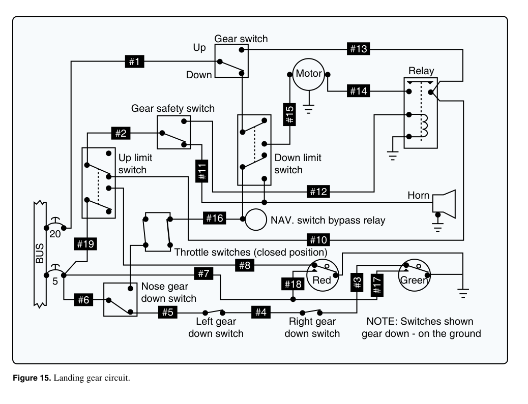
Figure 15. Landing gear circuit. Source: FAA-CT-8080-4G, Airman Knowledge Testing Supplement for Aviation Maintenance Technician — General, Airframe, and Powerplant; and Parachute Rigger.
What This FAA Diagram Shows
This diagram is a landing gear circuit. It includes several common aircraft electrical items that A&P students should recognize:
- A power bus
- Circuit protection
- Gear switches
- Limit switches
- A motor
- A relay
- A horn
- Red and green indicator lights
- Ground symbols
- Numbered circuit points
The diagram looks complicated because several systems are tied together:
- The landing gear motor circuit
- The gear warning horn circuit
- The gear position indication circuit
- The safety and limit switch circuit
The best way to read it is not to memorize every line. The best way is to break it into smaller sections.
Step 1: Find the Power Source
On the left side of the diagram, notice the BUS.
That is the power source for the circuit.
In many aircraft electrical diagrams, the bus is where power is distributed to different electrical systems. From there, power flows through circuit protection and then to switches, relays, lights, motors, or other loads.
In this diagram, you can see two circuit protection values near the bus:
20
5
These represent protected branches of the circuit. One branch feeds a higher-current portion of the circuit, and another branch feeds a lower-current portion.
A good first question is:
Where does power enter the circuit?
In this FAA figure, start at the BUS on the left.
Step 2: Look for the Load
A load is the component that uses electrical energy to do work.
In this diagram, the major loads include:
- The motor
- The horn
- The red indicator light
- The green indicator light
- The relay coil
The motor is near the top center of the diagram. That motor represents the landing gear motor. The horn is on the right side. The red and green lights are near the lower right.
When troubleshooting, identifying the load helps you understand the purpose of that part of the circuit.
For example:
- If the motor does not run, you would trace the motor circuit.
- If the horn does not sound, you would trace the warning horn circuit.
- If the gear indicator light does not illuminate, you would trace the indicator light circuit.
Step 3: Identify the Switches
This diagram has several switches. Some are manually controlled and others are position switches.
You can see:
- Gear switch
- Gear safety switch
- Up limit switch
- Down limit switch
- Throttle switches
- Nose gear down switch
- Left gear down switch
- Right gear down switch
These switches control when current can flow.
For example, a limit switch is used to stop or change circuit operation when the gear reaches a certain position. A gear down switch can be used to indicate that a gear leg is down and locked.
The note in the lower right says:
Switches shown gear down - on the ground
That note matters. It tells you the switch positions shown in the diagram. If you ignore that note, you can easily misread the circuit.
Step 4: Understand the Indicator Lights
At the lower right of the FAA diagram, you can see two indicator lights:
- Red
- Green
In a landing gear system, indicator lights help show gear position or unsafe conditions.
In general terms:
- A green light is commonly associated with gear down-and-locked indication.
- A red light is commonly associated with an unsafe or in-transit condition.
The exact meaning depends on the aircraft and the manual, but for reading the diagram, the important point is that these lights are loads controlled by switches in the gear circuit.
To understand an indicator light circuit, ask:
- Where does the light get power?
- Which switch completes or interrupts the circuit?
- Where does the circuit go to ground?
Step 5: Follow One Circuit at a Time
This is the most important habit.
Do not try to read the entire diagram at once.
Instead, pick one part of the circuit and trace it.
For example, to study the green light circuit, look near the lower right and trace the path through:
Green light → gear down switches → ground / return path
To study the motor circuit, start at the bus and trace toward:
BUS → gear switch → relay / limit switches → motor → ground
To study the horn circuit, trace toward:
BUS → throttle switches / gear switches → horn → ground
Each of those is a smaller circuit inside the larger diagram.
Step 6: Use the Numbered Labels
The FAA diagram includes numbered black labels such as:
#1
#2
#3
#4
#5
#6
...
These numbers are important because FAA knowledge test questions may refer to specific points, wires, or locations in the figure.
If a question asks about a numbered point, do not jump to the answer. First locate the number on the diagram, then determine what part of the circuit it belongs to.
Ask:
- Is this point on the power side?
- Is this point near a switch?
- Is this point part of the motor circuit?
- Is this point part of the warning circuit?
- Is this point part of the indicator light circuit?
- Is this point connected to ground?
That method helps you avoid guessing.
Step 7: Pay Attention to Grounds
Ground symbols appear in several places in this diagram.
A ground symbol means that part of the circuit returns to the aircraft structure or another return path, depending on the aircraft design.
A circuit needs a complete path:
Power source → control device → load → return path
If the return path is open or poor, the component may not work even if voltage is present on the power side.
That is why A&P students should always check both sides of the circuit:
- The power side
- The ground or return side
Example Troubleshooting Question
Let’s say the green gear light does not come on.
A logical troubleshooting process might be:
- Check whether power is available to the indication circuit.
- Check the green light itself.
- Check the gear down switches.
- Check whether the circuit has a valid ground path.
- Check for an open wire or poor connection.
The diagram helps you decide where to test instead of randomly replacing parts.
Another Example: Gear Motor Does Not Run
If the landing gear motor does not run, you could trace:
BUS → gear switch → limit switches → relay → motor → ground
Then ask:
- Is power available at the bus?
- Is the gear switch passing power?
- Are the limit switches in the correct position?
- Is the relay operating?
- Is the motor receiving power?
- Does the motor have a good ground?
That is the practical value of a wiring diagram.
Common Mistakes When Reading FAA Diagrams
Mistake 1: Ignoring the Notes
The note says the switches are shown with the gear down and on the ground. That changes how you interpret the switch positions.
Mistake 2: Reading the Whole Diagram at Once
Break the diagram into smaller circuits: motor, horn, red light, green light, relay, and switches.
Mistake 3: Forgetting About Grounds
If a component has power but no return path, it will not operate properly.
Mistake 4: Not Identifying the Load
Always find the component that is supposed to do work: a motor, light, horn, relay coil, or other electrical load.
Mistake 5: Guessing Based on Memory
FAA test figures are meant to be read carefully. Use the figure, not just memory.
Study Tip for A&P Students
When studying a wiring diagram, print it out and highlight one circuit at a time.
Use different colors for:
- Power supply
- Switch path
- Load
- Ground path
Then write a simple sentence:
Power leaves the bus, passes through a switch, operates the load, and returns to ground.
If you can explain the circuit in one sentence, you understand it much better.
Final Thoughts
Aircraft wiring diagrams are just maps. The FAA testing supplement figures can look crowded, but the same basic rules apply:
- Find the power source.
- Find the load.
- Identify the switches and relays.
- Follow one wire path at a time.
- Pay attention to notes.
- Do not ignore grounds.
For A&P students, the goal is not to memorize every line. The goal is to learn how to read the diagram logically and use it to answer questions or troubleshoot problems.
References
- FAA-CT-8080-4G, Airman Knowledge Testing Supplement for Aviation Maintenance Technician — General, Airframe, and Powerplant; and Parachute Rigger, Figure 15, Landing gear circuit.
- FAA-H-8083-30B, Aviation Maintenance Technician Handbook — General.
- FAA-H-8083-31B, Aviation Maintenance Technician Handbook — Airframe.
- AC 43.13-1B, Chapter 11, Aircraft Electrical Systems.
- Always use the current aircraft manufacturer maintenance manual, wiring diagram manual, or illustrated parts data when working on a specific aircraft.